
Articles récents
STM32 : Conversion analogique-numÃĐrique
Le STM32 possÃĻde un ADC (Analog to Digital Converter) permettant de mesurer des tensions. Nous voir comment l'utiliser et le paramÃĐtrer.
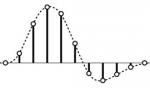
Le datasheet spÃĐcifie que mon STM32F401EE dispose d'un ADC de 12 bits, 2,4 Mhz jusqu'Ã 16 canaux!
1) Initialisation et configuration
Le STM32CubeMX permet de paramÃĐtrer l'ADC assez facilement. Pour cela, sous Analog choisir ADC1. Ensuite, la liste des canaux apparaÃŪt. Ceux qui sont en rouge sont dÃĐjà rÃĐservÃĐs. Si on sÃĐlectionne IN0, on voit que PA0 est initialisÃĐ sur ce canal sur la reprÃĐsentation graphique du microcontrÃīleur.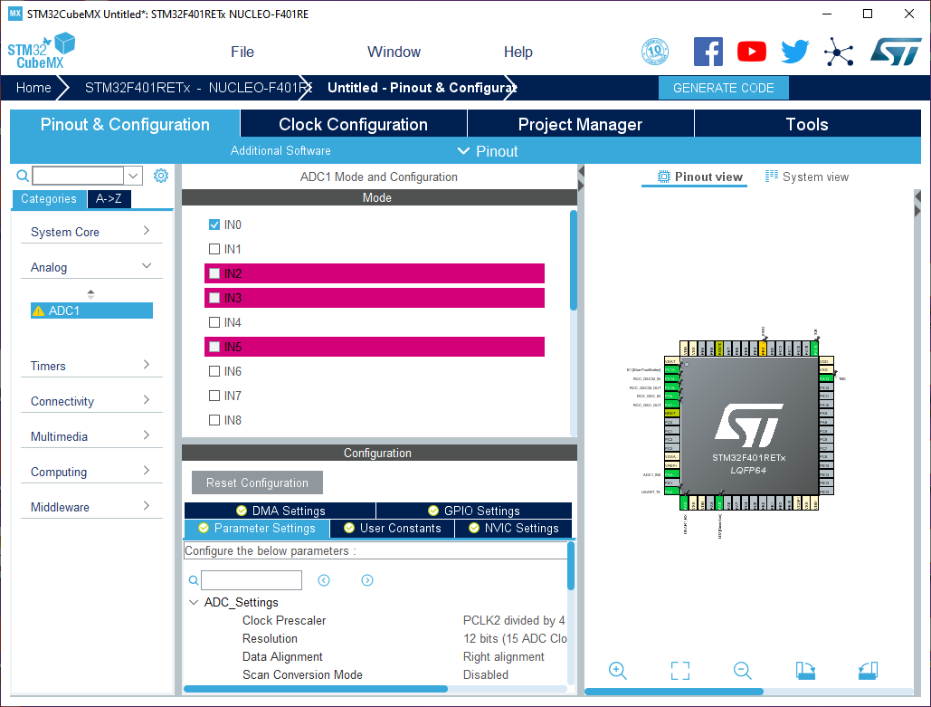
Dans Parameters Settings, mettre le Continuous Conversion Mode à enabled. Ensuite, et comme je vous ai montrÃĐ dans les articles prÃĐcÃĐdents, dans l'onglet Project Manager, il suffit de crÃĐer un projet avec la toolchain MDK-ARM. On peut alors ouvrir le projet dans l'IDE Keil UVision.
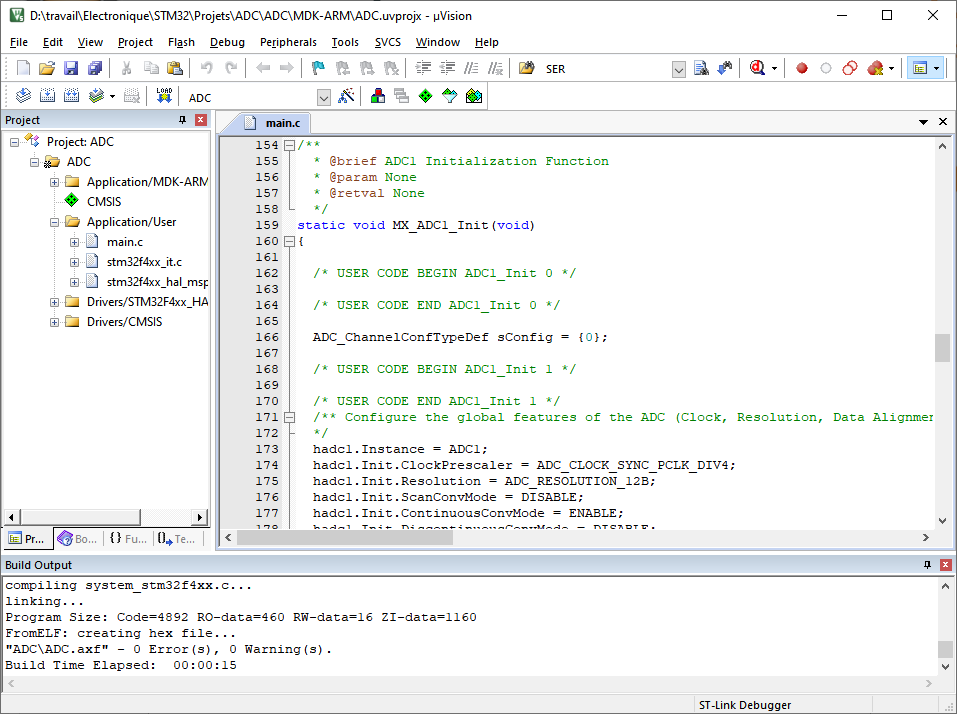
Si on observe un peu, on observe l'ajout de MX_ADC1_Init(); dans la fonction main() et d'une nouvelle variable ADC_HandleTypeDef hadc1;
 void MX_ADC1_Init(void)
{

  /* USER CODE BEGIN ADC1_Init 0 */

  /* USER CODE END ADC1_Init 0 */

  ADC_ChannelConfTypeDef sConfig = {0};

  /* USER CODE BEGIN ADC1_Init 1 */

  /* USER CODE END ADC1_Init 1 */
  /** Configure the global features of the ADC (Clock, Resolution, Data Alignment and number of conversion)
  */
  hadc1.Instance = ADC1;
  hadc1.Init.ClockPrescaler = ADC_CLOCK_SYNC_PCLK_DIV4;
  hadc1.Init.Resolution = ADC_RESOLUTION_12B;
  hadc1.Init.ScanConvMode = DISABLE;
  hadc1.Init.ContinuousConvMode = ENABLE;
  hadc1.Init.DiscontinuousConvMode = DISABLE;
  hadc1.Init.ExternalTrigConvEdge = ADC_EXTERNALTRIGCONVEDGE_NONE;
  hadc1.Init.ExternalTrigConv = ADC_SOFTWARE_START;
  hadc1.Init.DataAlign = ADC_DATAALIGN_RIGHT;
  hadc1.Init.NbrOfConversion = 1;
  hadc1.Init.DMAContinuousRequests = DISABLE;
  hadc1.Init.EOCSelection = ADC_EOC_SINGLE_CONV;
  if (HAL_ADC_Init(&hadc1) != HAL_OK)
  {
    Error_Handler();
  }
  /** Configure for the selected ADC regular channel its corresponding rank in the sequencer and its sample time.
  */
  sConfig.Channel = ADC_CHANNEL_0;
  sConfig.Rank = 1;
  sConfig.SamplingTime = ADC_SAMPLETIME_3CYCLES;
  if (HAL_ADC_ConfigChannel(&hadc1, &sConfig) != HAL_OK)
  {
    Error_Handler();
  }
  /* USER CODE BEGIN ADC1_Init 2 */

  /* USER CODE END ADC1_Init 2 */

}
2) Mise en oeuvre de l'ADC
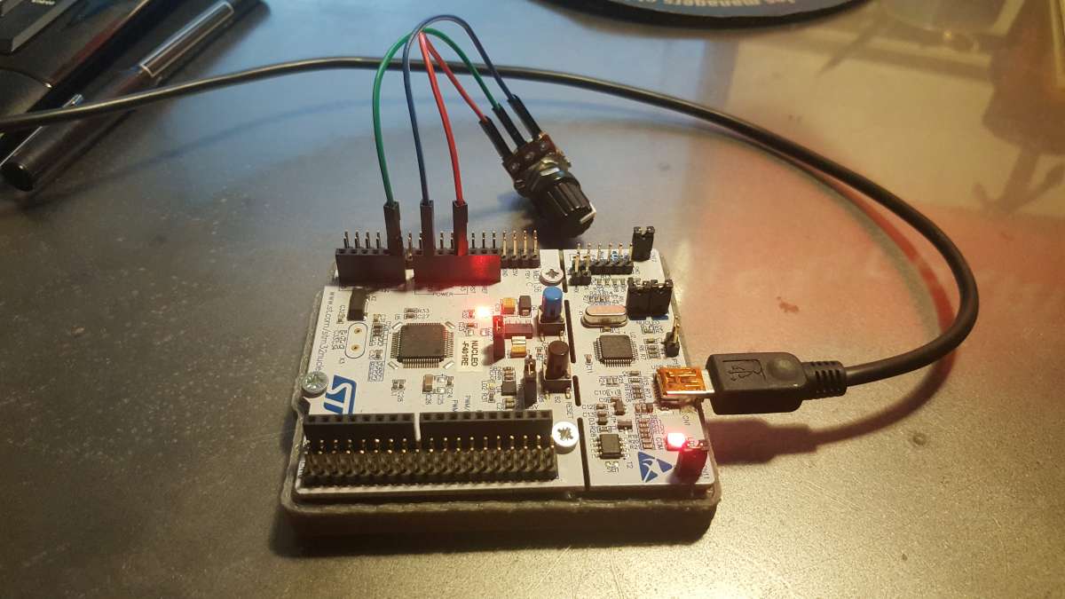
Toute la phase d'initialisation est terminÃĐe, passons à l'action. Prenons un potentiomÃĻtre de 10K afin de faire varier la tension sur PA0 entre 0V et 3.3V. Pour cela, il suffit d'utiliser le brochage de la carte Nucleo comme indiquÃĐ ci-dessous.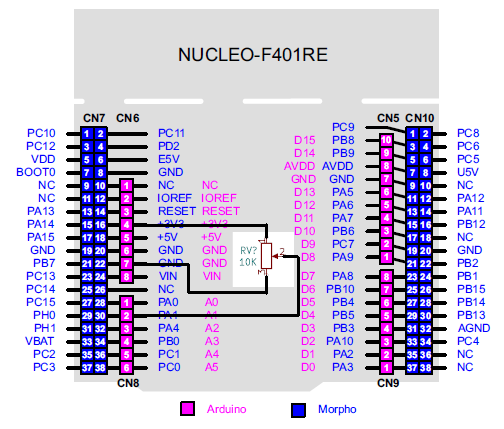
Le code de la fonction principale est tel que:
int main(void)
{
/* MCU Configuration--------------------------------------------------------*/
/* Reset of all peripherals, Initializes the Flash interface and the Systick. */
HAL_Init();
/* Configure the system clock */
SystemClock_Config();
/* Initialize all configured peripherals */
MX_GPIO_Init();
MX_ADC1_Init();
MX_USART2_UART_Init();
HAL_ADC_Start(&hadc1);
/* Infinite loop */
while (1)
{
if (HAL_ADC_PollForConversion(&hadc1, 1000000) == HAL_OK)
{
ADCValue = HAL_ADC_GetValue(&hadc1);
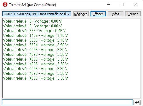
Voltage_Data= ADCValue*(3.3/4095);
sprintf(str, "Valeur relevÃĐ : %d - Voltage : %.2f Vrn", ADCValue, Voltage_Data);
HAL_UART_Transmit_IT(&huart2,(uint8_t*)str,strlen(str));
HAL_Delay(2000);
}
}
}
Ensuite, la fonction HAL_ADC_PollForConversion(&hadc1, 1000000) rÃĐalise une temporisation pour attente de la conversion de la mesure rÃĐalisÃĐe par l'ADC. On peut lire la mesure par l'intermÃĐdiaire de la fonction HAL_ADC_GetValue(&hadc1).
Ce qui donne sur le terminal de la liaison sÃĐrie:
Voici le programme complet:
/* USER CODE BEGIN Header */
/**
******************************************************************************
* @file : main.c
* @brief : Main program body
******************************************************************************
* @attention
*
* ÂĐ Copyright (c) 2020 STMicroelectronics.
* All rights reserved.
*
* This software component is licensed by ST under BSD 3-Clause license,
* the "License"; You may not use this file except in compliance with the
* License. You may obtain a copy of the License at:
* opensource.org/licenses/BSD-3-Clause
*
******************************************************************************
*/
/* USER CODE END Header */
/* Includes ------------------------------------------------------------------*/
#include "main.h"
#include "stdio.h"
#include "string.h"
/* Private includes ----------------------------------------------------------*/
/* USER CODE BEGIN Includes */
/* USER CODE END Includes */
/* Private typedef -----------------------------------------------------------*/
/* USER CODE BEGIN PTD */
/* USER CODE END PTD */
/* Private define ------------------------------------------------------------*/
/* USER CODE BEGIN PD */
/* USER CODE END PD */
/* Private macro -------------------------------------------------------------*/
/* USER CODE BEGIN PM */
/* USER CODE END PM */
/* Private variables ---------------------------------------------------------*/
ADC_HandleTypeDef hadc1;
UART_HandleTypeDef huart2;
/* USER CODE BEGIN PV */
double Voltage_Data;
char str[15];
uint32_t ADCValue;
/* USER CODE END PV */
/* Private function prototypes -----------------------------------------------*/
void SystemClock_Config(void);
static void MX_GPIO_Init(void);
static void MX_ADC1_Init(void);
static void MX_USART2_UART_Init(void);
/* USER CODE BEGIN PFP */
/* USER CODE END PFP */
/* Private user code ---------------------------------------------------------*/
/* USER CODE BEGIN 0 */
/* USER CODE END 0 */
/**
* @brief The application entry point.
* @retval int
*/
int main(void)
{
/* USER CODE BEGIN 1 */
/* USER CODE END 1 */
/* MCU Configuration--------------------------------------------------------*/
/* Reset of all peripherals, Initializes the Flash interface and the Systick. */
HAL_Init();
/* USER CODE BEGIN Init */
/* USER CODE END Init */
/* Configure the system clock */
SystemClock_Config();
/* USER CODE BEGIN SysInit */
/* USER CODE END SysInit */
/* Initialize all configured peripherals */
MX_GPIO_Init();
MX_ADC1_Init();
MX_USART2_UART_Init();
/* USER CODE BEGIN 2 */
HAL_ADC_Start(&hadc1);
/* USER CODE END 2 */
/* Infinite loop */
/* USER CODE BEGIN WHILE */
while (1)
{
if (HAL_ADC_PollForConversion(&hadc1, 1000000) == HAL_OK)
{
ADCValue = HAL_ADC_GetValue(&hadc1);
Voltage_Data= ADCValue*(3.3/4095);
sprintf(str, "Valeur relevÃĐ : %d - Voltage : %.2f Vrn", ADCValue, Voltage_Data);
HAL_UART_Transmit_IT(&huart2,(uint8_t*)str,strlen(str));
HAL_Delay(2000);
}
/* USER CODE END WHILE */
/* USER CODE BEGIN 3 */
}
/* USER CODE END 3 */
}
/**
* @brief System Clock Configuration
* @retval None
*/
void SystemClock_Config(void)
{
RCC_OscInitTypeDef RCC_OscInitStruct = {0};
RCC_ClkInitTypeDef RCC_ClkInitStruct = {0};
/** Configure the main internal regulator output voltage
*/
__HAL_RCC_PWR_CLK_ENABLE();
__HAL_PWR_VOLTAGESCALING_CONFIG(PWR_REGULATOR_VOLTAGE_SCALE2);
/** Initializes the CPU, AHB and APB busses clocks
*/
RCC_OscInitStruct.OscillatorType = RCC_OSCILLATORTYPE_HSI;
RCC_OscInitStruct.HSIState = RCC_HSI_ON;
RCC_OscInitStruct.HSICalibrationValue = RCC_HSICALIBRATION_DEFAULT;
RCC_OscInitStruct.PLL.PLLState = RCC_PLL_ON;
RCC_OscInitStruct.PLL.PLLSource = RCC_PLLSOURCE_HSI;
RCC_OscInitStruct.PLL.PLLM = 16;
RCC_OscInitStruct.PLL.PLLN = 336;
RCC_OscInitStruct.PLL.PLLP = RCC_PLLP_DIV4;
RCC_OscInitStruct.PLL.PLLQ = 7;
if (HAL_RCC_OscConfig(&RCC_OscInitStruct) != HAL_OK)
{
Error_Handler();
}
/** Initializes the CPU, AHB and APB busses clocks
*/
RCC_ClkInitStruct.ClockType = RCC_CLOCKTYPE_HCLK|RCC_CLOCKTYPE_SYSCLK
|RCC_CLOCKTYPE_PCLK1|RCC_CLOCKTYPE_PCLK2;
RCC_ClkInitStruct.SYSCLKSource = RCC_SYSCLKSOURCE_PLLCLK;
RCC_ClkInitStruct.AHBCLKDivider = RCC_SYSCLK_DIV1;
RCC_ClkInitStruct.APB1CLKDivider = RCC_HCLK_DIV2;
RCC_ClkInitStruct.APB2CLKDivider = RCC_HCLK_DIV1;
if (HAL_RCC_ClockConfig(&RCC_ClkInitStruct, FLASH_LATENCY_2) != HAL_OK)
{
Error_Handler();
}
}
/**
* @brief ADC1 Initialization Function
* @param None
* @retval None
*/
static void MX_ADC1_Init(void)
{
/* USER CODE BEGIN ADC1_Init 0 */
/* USER CODE END ADC1_Init 0 */
ADC_ChannelConfTypeDef sConfig = {0};
/* USER CODE BEGIN ADC1_Init 1 */
/* USER CODE END ADC1_Init 1 */
/** Configure the global features of the ADC (Clock, Resolution, Data Alignment and number of conversion)
*/
hadc1.Instance = ADC1;
hadc1.Init.ClockPrescaler = ADC_CLOCK_SYNC_PCLK_DIV4;
hadc1.Init.Resolution = ADC_RESOLUTION_12B;
hadc1.Init.ScanConvMode = DISABLE;
hadc1.Init.ContinuousConvMode = ENABLE;
hadc1.Init.DiscontinuousConvMode = DISABLE;
hadc1.Init.ExternalTrigConvEdge = ADC_EXTERNALTRIGCONVEDGE_NONE;
hadc1.Init.ExternalTrigConv = ADC_SOFTWARE_START;
hadc1.Init.DataAlign = ADC_DATAALIGN_RIGHT;
hadc1.Init.NbrOfConversion = 1;
//hadc1.Init.DMAContinuousRequests = DISABLE;
hadc1.Init.EOCSelection = ADC_EOC_SINGLE_CONV;
hadc1.Init.EOCSelection = DISABLE;
if (HAL_ADC_Init(&hadc1) != HAL_OK)
{
Error_Handler();
}
/** Configure for the selected ADC regular channel its corresponding rank in the sequencer and its sample time.
*/
sConfig.Channel = ADC_CHANNEL_0;
sConfig.Rank = 1;
sConfig.SamplingTime = ADC_SAMPLETIME_3CYCLES;
if (HAL_ADC_ConfigChannel(&hadc1, &sConfig) != HAL_OK)
{
Error_Handler();
}
/* USER CODE BEGIN ADC1_Init 2 */
/* USER CODE END ADC1_Init 2 */
}
/**
* @brief USART2 Initialization Function
* @param None
* @retval None
*/
static void MX_USART2_UART_Init(void)
{
/* USER CODE BEGIN USART2_Init 0 */
/* USER CODE END USART2_Init 0 */
/* USER CODE BEGIN USART2_Init 1 */
/* USER CODE END USART2_Init 1 */
huart2.Instance = USART2;
huart2.Init.BaudRate = 115200;
huart2.Init.WordLength = UART_WORDLENGTH_8B;
huart2.Init.StopBits = UART_STOPBITS_1;
huart2.Init.Parity = UART_PARITY_NONE;
huart2.Init.Mode = UART_MODE_TX_RX;
huart2.Init.HwFlowCtl = UART_HWCONTROL_NONE;
huart2.Init.OverSampling = UART_OVERSAMPLING_16;
if (HAL_UART_Init(&huart2) != HAL_OK)
{
Error_Handler();
}
/* USER CODE BEGIN USART2_Init 2 */
/* USER CODE END USART2_Init 2 */
}
/**
* @brief GPIO Initialization Function
* @param None
* @retval None
*/
static void MX_GPIO_Init(void)
{
GPIO_InitTypeDef GPIO_InitStruct = {0};
/* GPIO Ports Clock Enable */
__HAL_RCC_GPIOC_CLK_ENABLE();
__HAL_RCC_GPIOH_CLK_ENABLE();
__HAL_RCC_GPIOA_CLK_ENABLE();
__HAL_RCC_GPIOB_CLK_ENABLE();
/*Configure GPIO pin Output Level */
HAL_GPIO_WritePin(LD2_GPIO_Port, LD2_Pin, GPIO_PIN_RESET);
/*Configure GPIO pin : B1_Pin */
GPIO_InitStruct.Pin = B1_Pin;
GPIO_InitStruct.Mode = GPIO_MODE_IT_FALLING;
GPIO_InitStruct.Pull = GPIO_NOPULL;
HAL_GPIO_Init(B1_GPIO_Port, &GPIO_InitStruct);
/*Configure GPIO pin : LD2_Pin */
GPIO_InitStruct.Pin = LD2_Pin;
GPIO_InitStruct.Mode = GPIO_MODE_OUTPUT_PP;
GPIO_InitStruct.Pull = GPIO_NOPULL;
GPIO_InitStruct.Speed = GPIO_SPEED_FREQ_LOW;
HAL_GPIO_Init(LD2_GPIO_Port, &GPIO_InitStruct);
}
/* USER CODE BEGIN 4 */
/* USER CODE END 4 */
/**
* @brief This function is executed in case of error occurrence.
* @retval None
*/
void Error_Handler(void)
{
/* USER CODE BEGIN Error_Handler_Debug */
/* User can add his own implementation to report the HAL error return state */
/* USER CODE END Error_Handler_Debug */
}
#ifdef USE_FULL_ASSERT
/**
* @brief Reports the name of the source file and the source line number
* where the assert_param error has occurred.
* @param file: pointer to the source file name
* @param line: assert_param error line source number
* @retval None
*/
void assert_failed(uint8_t *file, uint32_t line)
{
/* USER CODE BEGIN 6 */
/* User can add his own implementation to report the file name and line number,
tex: printf("Wrong parameters value: file %s on line %drn", file, line) */
/* USER CODE END 6 */
}
#endif /* USE_FULL_ASSERT */
/************************ (C) COPYRIGHT STMicroelectronics *****END OF FILE****/
Conclusion
Voici une nouvelle ÃĐtape de franchie dans notre dÃĐcouverte du STM32. Finalement, l'utilisation des ADC du STM32 est relativement simple si on utilise le STM32CubeMX. Sans cet outil, il faudra configurer vous mÊme les diffÃĐrentes librairies et initialiser la fonction MX_ADC1_Init() ce qui n'est pas si ÃĐvident. Donc je recommande vivement, l'utilisation du CubeMx pour ÃĐviter trop de tracas inutiles.N'hÃĐsitez à mettre un commentaire si cet article vous a ÃĐtÃĐ utile. (Cela me motivera pour continuer :-))
|
|
Bob Doritique - 2022-11-13 23:25:48
Bonjour. Il s'agit de la resolution de l'ADC. De memoire cela est parametrable. |
© 2025 www.doritique.fr par Robert DORIGNY
Bnnjour. Merci beaucoup pour votre aide et votre article Cependant j'aimerai savoir ici: VoltageDataADCValue3.34095 pourquoi vous avez choisi 4095 Merci d'avance.